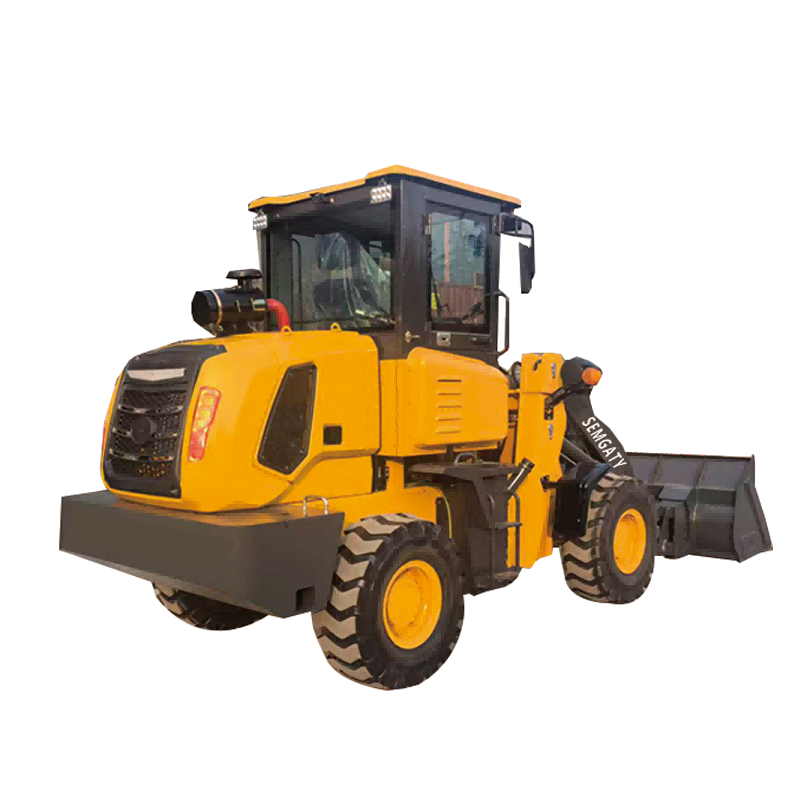
| parameter |
| Performance | 1 | Rated loading | 1500KG |
| 2 | Overall weight | 3650KG |
| 3 | Bucket capacity | 0.7m3 |
| 4 | Maximum traction force | 80Kn |
| 5 | Maximum breakout force | 38Kn |
| 6 | Maximum grade ability | 25℃ |
| 7 | Maximum dump height | 3200mm |
| 8 | Maximum dump reach | 800mm |
| 9 | Overall dimension (L×W×H) | 5800*1810*2650mm |
| Engine | 10 | Model | Yuchai |
| 11 | Type | lnline / Water cooling /Dry cylinder /Injection |
| 13 | Rated power | 42kw-2400r/min |
| 14 | Maximum torque | 147N.M |
| 15 | Emission standards | National II |
| Transmission system | 16 | Torque converter | Single-stage four-element twin-turbine torque converter |
| 17 | Gearbox mode | Planetary power transmission |
| 18 | Gears | 2forward shift 2reverse shift |
|
| 19 | Maximum speed | 25Km/h |
| Drive axles | 20 | Main reducing spiral | Bevel gear grade 1reduction |
| 21 | Decelerating mode | Planetary reduction grade 1 |
|
| 22 | Wheel base (mm) | 2250mm |
| 23 | Wheel tread | 1410mm |
| Hydraulic system | 2222222 24 | System working pressure | 16MPa |
| 25 | Boom lifting time | 8.9s |
| 26 | Total time | 10±0.2s |
| Brake system | 27 | Service brake | Four-wheel brake with oil cap and disc |
|
| 28 | Parking brake | Manual disc type |
| Tyre | 29 | Type specification | 20.5—16 |
| 30 | Front tyre pressure | 0.4Mpa |
| 31 | Rear tyre pressure | 0.35Mpa |
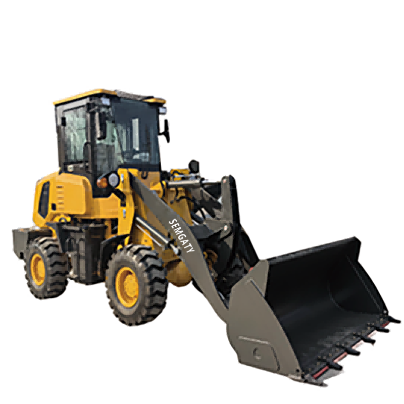
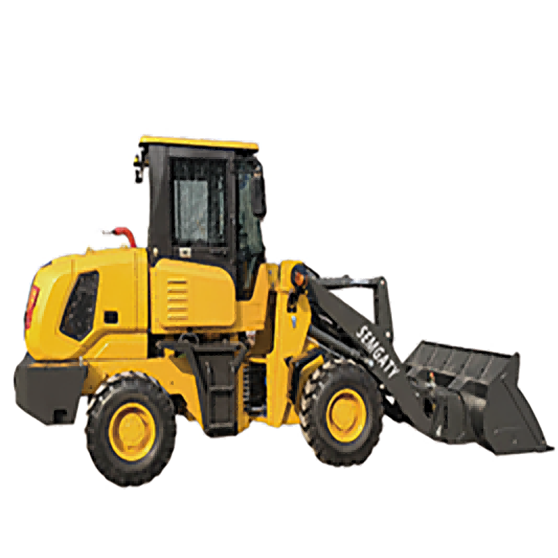
A wheel loader is a type of earthmoving and transporting machinery widely used in engineering projects and urban construction, including highways, railways, ports, docks, coal mines, mines, water conservancy projects, and national defense projects. It plays a vital role in reducing labor intensity, accelerating construction speed, and improving project quality.
A loader typically consists of a frame, power transmission system, traveling mechanism, working device, steering and braking system, hydraulic system, and control system. The power from engine 1 is transmitted to gearbox 14 via torque converter 2, and then the gearbox transmits the power to the front and rear axles 10 via drive shafts 13 and 16 respectively, driving the wheels. The internal combustion engine power also drives the hydraulic pump 3 via a transfer case. The working device consists of boom 6, rocker arm 7, connecting rod 8, bucket 9, boom hydraulic cylinder 12, and rocker arm hydraulic cylinder 5. One end of the boom is hinged to the frame, and the other end is fitted with the bucket. The boom's raising and lowering is driven by the boom hydraulic cylinder, and the bucket's tilting is achieved by the bucket hydraulic cylinder via the rocker arm and connecting rod. The frame 11 consists of front and rear sections connected by a hinge pin 4. Steering is achieved by the steering hydraulic cylinder allowing the front and rear frames to rotate relative to each other around the hinge pin.
Principles
Loaders can be divided into: power system, mechanical system, hydraulic system, and control system. As an organic whole, the performance of a loader depends not only on the performance of its mechanical components but also on the performance of its hydraulic and control systems.
Power System: Loaders are generally powered by diesel engines. Diesel engines are reliable, have a strong power characteristic curve, and are fuel-efficient, meeting the requirements of loaders operating under harsh conditions and with varying loads.
Mechanical System: This mainly includes the traveling device, steering mechanism, and working device.
Hydraulic System: This system converts the engine's mechanical energy into hydraulic energy using fuel as a medium through an oil pump, and then transmits this hydraulic energy to cylinders, hydraulic motors, etc., converting it back into mechanical energy.
Control System: The control system controls the engine, hydraulic pump, multi-way directional valves, and actuators. The hydraulic control drive mechanism, within the hydraulic control system, is the device that converts small amounts of electrical or mechanical energy into powerful hydraulic and mechanical energy. It consists of hydraulic power amplifiers, hydraulic actuators, and a load, and is the core of the hydraulic system for static and dynamic analysis.
With technological innovation, our product configuration and parameters will continue to change without notice;
if there is any doubt, the specific confirmation of our international trade sales shall prevail;